
Hydrostatic Support Actuator | Precision Hydraulic Actuator for Press Systems
Quick Inquiry
description
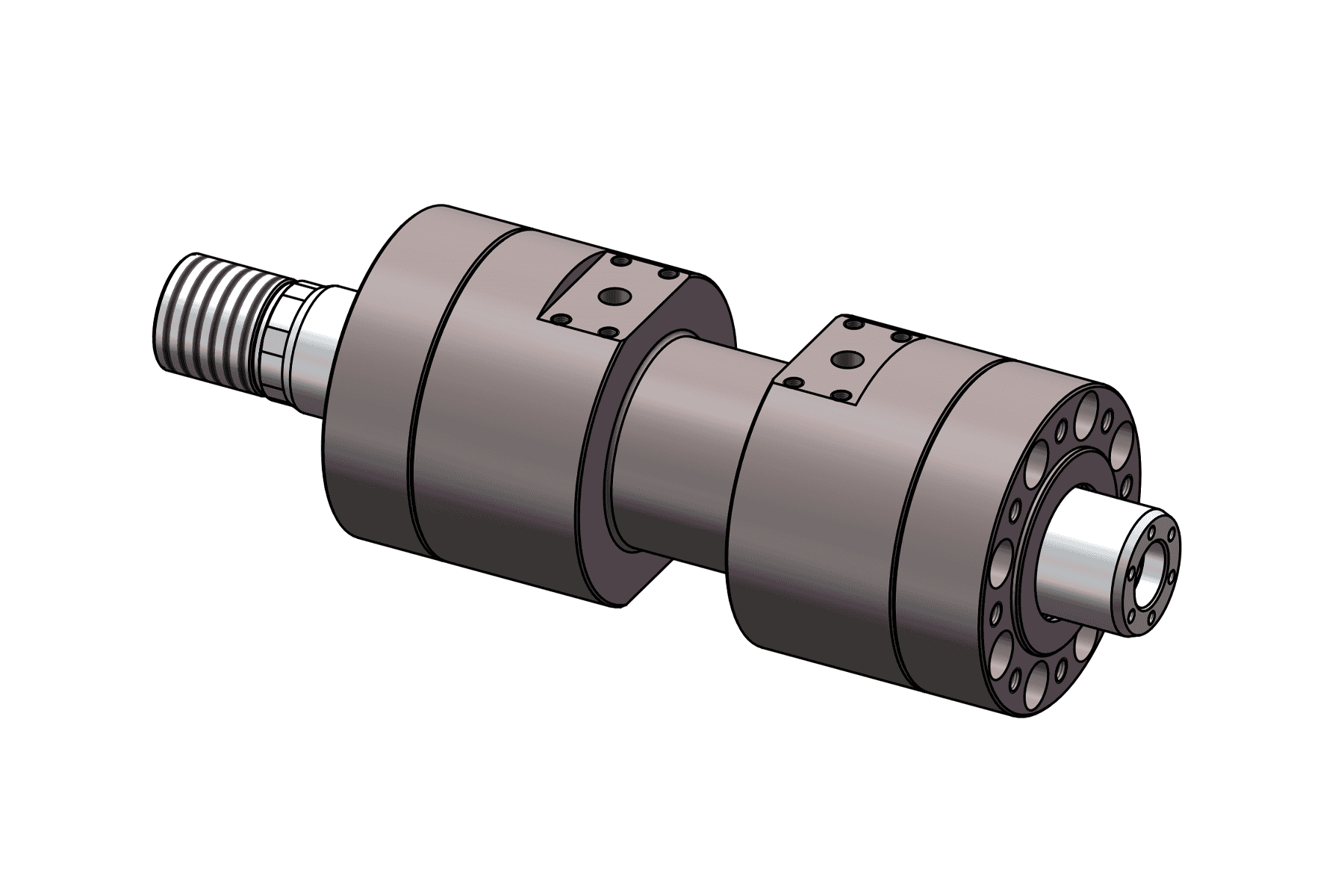
Hydrostatic Support Actuator is a precision hydraulic actuator designed for stable load support, smooth motion control, and reliable performance in heavy-duty press and industrial automation applications. The drawing shows a compact cylindrical structure with multiple mounting and thread specifications, making it suitable for customized mechanical integration.
This actuator series is available in multiple structural configurations, including square actuator, integrated manifold hydrostatic support actuator, intermediate hinge actuator, non-equal diameter actuator, double-end hinged actuator, and four-column press cylinder. These options help meet different installation and force transmission requirements in hydraulic systems.
According to the dimensional table, the product range covers cylinder inner diameters from 25 mm to 200 mm, with recommended tube inner diameter ranges and multiple dimensional parameters such as stroke, A, B, C, D, E, S, thread sizes, and overall length formulas. The drawing notes also indicate that 3D files are available on request, and the actuator can be customized for integrated blocks, servo valve manifolds, and rod-end connection forms.
gallery
Specifications
| Parameter | Specification |
|---|---|
| Product Name | Hydrostatic Support Actuator |
| Product Type | Hydraulic Actuator / Hydraulic Support Cylinder |
| Main Application | Press systems, hydraulic support systems, industrial automation |
| Available Configurations | Square Actuator; Integrated Manifold Hydrostatic Support Actuator; Intermediate Hinge Actuator; Non-Equal Diameter Actuator; Double-End Hinged Actuator; Four-Column Press Cylinder |
| Cylinder Inner Diameter (d1) | 25 mm, 30 mm, 40 mm, 50 mm, 63 mm, 80 mm, 100 mm, 125 mm, 160 mm, 200 mm |
| Recommended Tube Inner Diameter (D) | 29–47 mm, 34–52 mm, 44–67 mm, 54–77 mm, 67–87 mm, 84–117 mm, 104–147 mm, 129–172 mm, 164–217 mm, 204–277 mm |
| Stroke | 35 mm or 50 mm depending on model; some overall dimensions are calculated as formulas based on stroke |
| Dimension A | 19–179 mm |
| Dimension B | 68–344 mm |
| Dimension C | 86–408 mm |
| Dimension D | 9–29.5 mm |
| Dimension E | 21–193.5 mm |
| Dimension S | 20–192.5 mm |
| MA Thread | M6 to M30 |
| MB | 2.5 to 10 |
| MC Thread | M20×1.5 to M180×4 |
| MD Thread | M6 to M20 |
| MF Thread | M12 to M48 |
| MG Thread | M10 to M26 |
| MH Thread | M5 to M16 |
| L1 | 22–220 mm |
| L2 | 45+Stroke to 253+Stroke |
| L3 | 33+2×Stroke to 180+2×Stroke |
| L4 | 167+2×Stroke to 710+2×Stroke |
| L5 | 13+Stroke |
| L6 | 36–48 mm |
| L7 | 15–45 mm |
| L8 | 225+4×Stroke to 976+4×Stroke |
| Customization | Integrated block and servo valve manifold can be customized; rod-end connection form can also be customized; non-standard customization supported |
| Technical Support | 3D file available upon request |
